Search This Blog

Tuesday, December 16, 2008

The Completed Frame


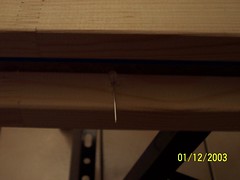
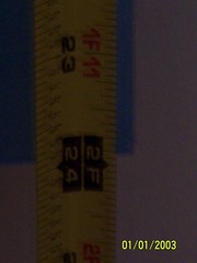
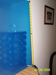
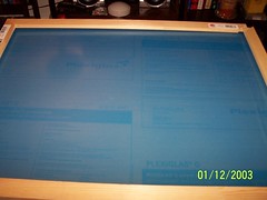
This is the completed set up. I don't have any experience or tools with woodworking so building a wooden frame from scratch would have been to costly and time consuming. To overcome that difficulty I chose PVC pipe. I bought 40 feet of 1.5 inch pipe, 6 t joints, 2 crosses and 8 90 degree elbows. I didn't take into account the extra length of the joints - I thought these distances would be minimal. However, with the diameter of the pipe I chose this judgment proved wrong as these joints added significant length to the frame. This meant I had to adjust my original measurements, cut the pipe more times than I care to mention ( actually about 3 times on certain pipes) and I need to measure the angle. The original design was meant for a 35 degree angle at the part of the base closest to the user. At the moment I have not glued the pipes together. This is because the only way to get a projector to finish the project is to borrow one from the McNair program at my university (FIU). So, I'll need to have helpers to steady the base to keep the multi touch display from falling. Once I can get a projector at my house (If anyone wants to donate an old working one I'll take it), then I'll fix the pipes in place. I can't wait to get this thing running! I might be able to conduct a mouse test in the mean time at my house. This would mean I'll test the compliant surfaces I've been working on and verify that the screen is fully visible to the camera. My calculations hint that a height of 36" should be enough to get a sloped screen fully in view. I should be verfying all this shortly.
In the mean time I'll be seeing how long the pipe frame can hold it's own weight. I obviously won't have the display on it!

Wednesday, November 5, 2008

Errors Compound

I was wrong! The web-cam I converted to view the IR spectrum was not ruined. How could I overlook this minor mistake for so long? I'll tell you how,I simply, and incorrectly, assumed it was the lens. This has been my greatest blunder of the entire project, costing me $20 from my shoestring budget! I'm not proud to say it, but it needs to be documented.  I discovered that the cam worked perfectly. As I began to inspect the cam I found that the focus ring could rotate. Once I had found the driver (which was no easy task ) I was able to refine the image to clarity.
By the way if you are using a Creative Instant WebCam model: VF-0040 and want to save time click here for the driver.
At the same time, against my better judgment, I decided to power the frame from the my laptop's USB port. This was the image I saw. I still hadn't completed the focusing but I got so excited I impetuously captured an image! This is much brighter than the images Juan and me took with our unmodified cameras. It also proved me wrong. I was of the mind that a measily 5.5V the USB laptop power line have the Amperage or, quite frankly, the testicular fortitude to drive 66 LED's. I'm quickly learning that I don't know everything, and that a project like this leaves you looking at the world with new eyes. So, here I am, blogging about my wonderful achievements. Amazed by the ignorance and absentmindedness I've accumulated over the years- and wondering if, after all this, I'm really just a mountebank- a fraud, a scheister. How can I teach others that which I don't know? Honestly, I can't be sure of everything- yet, but I am sure that this project will not stop until completed. I'll end this post with an image of the camera in focus. There is no IR burst - we already know it can pick that up. What I haven't proven- until now, is that the webcam can focus and capture a great picture! By the end of this part of the project I was glad I took a chance and listend to my instinct. I could power the frame from my laptop, I could focus the camera, and I can use a single computer to power the entire display. Maybe I'm not a mountebank seeking to deceive all who enter this site with bright eyed dowey eyes. I guess what it really comes down to is how much you're willing to learn - about trusting instinct, how much you really know about a subject, or how open minded you are to explore nature.

Wednesday, October 29, 2008

1st Busline successful!

Alright, so this is my dorky video of me documenting the second "official" test run of the bus line. I've soldered all the LED's and resistors together. This vid. shows the full row lit up - should be all 33. I'm so proud! :) I know the video isn't the best but it's all I got for now.

Concerning the Bus line

So, a few minutes ago I rigged up and successfully tested a USB connected wall transformer to 1 set of 3 LED's + 1 resistor. Now, it's not fully tested because I need to see if this will be enough to run the entire line but in theory it should be. It is putting out 5V at 1 Amp.
The red wire is connected to pin 1 (+5 live) of the USB and the black wire (0V i.e ground) is connected to pin 4. Pins 2 (Data -5V) and 3 (Data +5V) are for running data - at the moment I'm not concerned with that.
The attached video shows test 1, it's a bit long at 42 seconds so I wouldn't blame you for skipping ahead a few seconds here and there. The point of this test is to show that the wall transformer can pass enough voltage and current through 1 set of the LED's without blowing all the components or generating excess heat. There was no excess heat felt and I think it worked brilliantly for a first test. In the video you see my plugging in the USB end into the transformer connected to the wall and then I pan over to the LED's just before I insert the power connection fully. The light being shown is Infra-red light and not visible to the naked eye. Here it is visible because of the nature of digital cameras and their CCD's sensisitivity to the IR range. With any luck this will be powering the entire display by the end of the week!

Last nights Soldering Party


Last night Juan, Arian and me worked on the frame some. We started by placing the LED's with correct polarity into the baffles. Once we checked they were right we hot glued them in place. After cleaning the leads to the LED's we then prepped them to be soldered. After bending the leads on each of the 66 LED's we ran two wires across the one side of the frame. These will act as a "bus" for electrons to ride into the LED's sets and complete a circuit.
We were able to solder 33 LED's last night and test 1 set of 3 + resistor through the bus line. It worked great. There was only one big problem left to solve - how to we get power from the wall into the bus line?

Tuesday, October 28, 2008

Sunday night LED party!

This is an image of me soldering some electrical components together. We are soldering 66 LED's though we haven't quite finished yet. We are soldering them in sets of 3's with a resistor attached.
Each set connects all 3 LED's and the resistor in series. Each set of 3 is connected in parallel with every other set of 3. I've provided a really poorly hand drawn diagram of the circuit. It's only part of the circuit, enough to get the gist of what's going on. If you are building your own table and would like an easy way of working the LED circuit then this site is for you: http://led.linear1.org/led.wiz
It gives you an image similar to this (which is the actually circuit I'm using) and looks a lot better. This is what we were aiming to solder but we didn't finish that night and are looking forward to getting some more work done tonight. The most tedious part I would say was to make sure the LED's we were using were not defective or DOA. However, after all that we got to solder and power 1 set of 3 LED's and set them in the housing of the Baffle. I think it looks great!


Friday night Frame Party!

What better way to spend a Friday night than with your wife and old friend building and assembling a frame for your crazy project well until the wee hours of the night? I can't think of anything more fun. For those of you who have been following the blog you know that my friend Juan has been helping me a lot along the way with this project since July. Sadly, we are nearing the end of this project.
What follows now are some pictures of Juan and me assembling the frame, priming, and painting it. Enlarging the Slide show and turning the information on ( which means it should read info off - quite confusing but anyway) will show you the comments I have within the slide show.

Tuesday, October 21, 2008

Semi-finished product.


100_0587
Originally uploaded by m3trikpsi4s
In the image you can see the IR-LED fits snugly and the housing is supporting the LED.
Only thing left to do is clear out small splinters in the holes and paint the baffles. I will paint the side facing the acrylic white and the other sides black. By painting the front white (along with the holes) I will reflect more light into the acrylic. By painting the other sides black the paint will absorb the escaping energy and hopefully reduce any false readings due to light leakage.

Sanding some more!


100_0600
Originally uploaded by m3trikpsi4s
Now I have some good news to share and some bad news. Good news is there are now 2 baffles to line up the LED's 1 inch apart on either side of the acrylic.
Bad news? Cheap wood means splinters in the LED housings! What to do? Well, this little dremel attachment got rid of a lot of the splinters! However, there are still some smaller bits left over. This will be dealt with in an future post.

Baffling Templates


100_0590
Originally uploaded by m3trikpsi4s
So, after I got the first baffle drilled and sanded down enough to sit flat on a level surface I used it as a template. By sitting the first baffle on the second dowel and drilling through the holes and into the dowel I was able to get a second baffle. Although they weren't as perfectly centered as I had hoped it still saved time and kept the alignment of the future LED's.

Dremel to the rescue!


100_0597
Originally uploaded by m3trikpsi4s
My drill died during the build so I had to look to my dremel for help. This attachment wasn't much but it was better than nothing. Maybe I should have just heated an awl and punched through the wood instead?

Cheap wood


100_0594
Originally uploaded by m3trikpsi4s
So, the result of using cheap wood was learning a good lesson. Cheap wood splinters easy - that's why it's cheap! Also, I cracked part of my baffle because I forgot that darned center line.

FTIR LED Baffle 2


100_0586
Originally uploaded by m3trikpsi4s
This image is the start of the first baffle. Here I've marked off 1 inch increments with a compass and drilled through them. I forgot to make a center line which made all my holes off centered and haphazard. I've used a 2 or 3" clamp to help me hold the dowel steady while I drill.

FTIR LED Baffle


100_0588
Originally uploaded by m3trikpsi4s
I've recently gotten around to making my own baffles to hold the IR-LEDS and to direct the light into the acrylic waveguide. I tried to find a metal U or C channel but I couldn't find the right size anywhere! I decided to use 1/2" dowels from Home Depot - about 50 cents each. I would suggest using better wood or finding a metal channel if you can. The wood splintered and fractured easily, making it a nightmare to work. Here I've shown the led slipping into its new home :).

Friday, October 10, 2008

La Machine's latest and greatest Mechanical Monster!


That's right, you are seeing right, that is a giant 50' Mechanical spider parading itself down the high street in Liverpool, UK. The 50' mechanical beauty strutted its stuff on Sept. 6th and sprayed amazed onlookers with a water cannon in the back of the spider's abdomen! This amazing machine is called La Princess by the engineering group that created her La Machine.
There are more video's like this on youtube and also at www.liverpool-stories.com - Please comment if you have the time.

Sunday, October 5, 2008

FTIR Display Frame pt 3


100_0585
Originally uploaded by m3trikpsi4s
Here I'm checking the clearance of my IR led. The IR LED is Jameco part # 787667. I got 100 for $10! That's without the shipping of course. I was unlucky enough to have them shipped when gas prices were at a record high in July of 08 - $6 for shipping - I was fleeced!
So there is ample room using the canvas stretchers and 3/8" acrylic sheet.
There are notes here so feel free to click on the image and mouse around.
In the future I'd like to get an aluminum C-Channel to fit the led's into and to act as a baffle to focus the light. There is a great instructable I'm following that I will link shortly! Hope this helps anyone out there looking to build a multi touch display! I'll update again when I have more to say!

Measuring the Acrylic pt 2


100_0580
Originally uploaded by m3trikpsi4s
This is a better view of the measurement. Nothing special here - but there are two notes in case you are interested.

Measuring the Acrylic


100_0579
Originally uploaded by m3trikpsi4s
There are notes here as well. To access the notes click on the image and when it loads just mouse around.
Here the measure is 24". This is the way the actual frame will be laid out on the table.
Note the full dimensions are 24" by 32" so as to give a 4:3 ratio.

FTIR Display Frame pt 2


100_0584
Originally uploaded by m3trikpsi4s
Feel free to click on the image and then mouse around to read my notes.
I've put both acrylic panels together here. They are sandwiched by the wooden canvas stretchers / make shift display frame.
Best part of all - no wood cutting! I will have to drill and thread screws through but that should be a breeze!

I got the canvas stretchers at an art store called Utrecht in Miami. This is near Sunset Place on US 1, about a block away from Pearl. You should be able to get this at any art store or hobby store - search for Canvas stretchers. Also, you can locate an art store near you with these canvas stretchers by visiting www.fredrix.com. But any art store should have them in many different sizes. I found that although my acrylic is 24" by 32" that purchasing 32" by 26" actually fit the screen better.

Multi Touch Frame Part 1


100_0582
Originally uploaded by m3trikpsi4s
Being that have no real word working tools or experience I looked for a way around building my own frame.
Well, I found the perfect solution for me - Canvas stretchers! They come in various sizes and all you have to do is snap them together like wooden Lego's!
Also - the date is wrong. The batteries on my camera died and reset the date to its default setting. The camera is pretty old lol.
The size I'm using here are 24" by 32" for the back and 26" by 32" for the front.
I'm thinking of making the back also 26" by 32" as the arrangement I had in my mind didn't quite work out.

Acrylic Wave Guide and IR light.


DSCF5851
Originally uploaded by m3trikpsi4s
Juan was kind enough to take this picture while I made this little make shift baffle. There are notes in the picture so feel free to mouse over.

Sorry for the long over due update!

Wednesday, July 9, 2008

Videos of Turbine in Action

This is trial 1. As you can see I got off to a rough start.

This is trial 4 - you can see why I'm having trouble getting a good solid start.


This is trial 8 - the best trial to date. I will need to continue refining the pressure mechanism to get better results from the turbine.


So, what's happening here? Will this is running on the boundary layer effect. Basically, the molecules of a gas or liquid will rush into the chamber. Once they hit a disk on the runner part of the molecules surface will latch onto the surface of the disk and pull it with it. As this continues to happen energy is lost and the particle/ molecule will spiral in towards the center (where the exhaust valve is). This action drags the disk along with the particles and the disks are set into motion. This is what drives the runner and why no buckets or blades are needed.

If run in reverse ( say you use energy to turn the runner) and pump in the gas or liquid in through the exhaust valve - you are now running it as a compressor/ pump. In some models the turbine is strong enough to pump mud with rocks. As a matter of fact a few oil companies have been using these as pumps since the 60's. It's a great way to pump up oil with rocks and sludge!

TESLA TURBINE!

So, as some of you may remember, around spring of last year I had a failed attempt at building a Tesla Turbine. Obviously the problem was aiming too high for a proto-type (using aluminum disks 1 ft in diameter).
This time I took a page out of the instructables book at this page. Mr. Fixits over at instructables has come up with a really clever way to build a Tesla Turbine. I became so enamored with this build so much that I decided to build my own proto-type turbine almost identically. This would allow me to test the claim on the page and at the same time investigate my own doubts about a blade-less turbine.
By the way, I know this is interrupting the FTIR table but I have to do something while the parts get shipped!

This is a side view of the turbine. Basically just cd's I don't want in the cd case they came in. Also, there are some plastic washers in there I used as spacers.

I drilled a few holes with my dremel ( not sure the of diameter) to act as an exhaust port. The holes don't span the entire height - that's actually about the extent of it. This might be a problem as I'm not properly exhausting the water or air.


This is a view from the side - just a regular cd case. If you look closely you'll see the tope 2 cd's are at an angle - this is probably due to the nozzel. I wasn't able to mount it perfectly - this creates drag which drops the RPM's. I haven't yet gotten a tachymeter (I only did this today around 11 am) so I can't tell how many RPM's I might be losing.


This is the first nozzel mechanism. I used 2 nozzels. This connects directly to the faucet. I can use the control valve to vary the pressure feed into the turbine.


This is the full assembly. The little red thing would be the second nozzel. I hot glued that into the case ( which is where the friction comes in).


Thursday, June 19, 2008

Infra Red Web Cam 1st test


In a future post I will show how to take apart the Creative Web Cam Instant. Incidentally, creative is currently selling these for $7.99 US click here or here to see what I'm talking about. The second of the two I believe has better resolution.
So, what I'm showing here is the difference in the thickness of the visible light filter versus the clarity you get. Please note, I messed up the lens taking it out the first time. So if you do this, please have a file handy and file the lens out of its holder.
This First image is the camera using 1 square of unexposed film negative. This is the best I can get the camera - so now you can see why you should take better care extracting your lens.


The second shot down is me using 2 squares of unexposed film negative. You can see it's gotten blurrier. I believe part of the reason for this is because it takes time for the squares to settle on to each other. I did this in succession to get the shots as fast as I could. So, basically the negatives don't sit well, and the air between them acts to refract and reflect the light a bit causing this distortion when it finally hits the ccd chip. Also, remember the lens is messed up!

O.K. so in this shot I'm using 3 slivers of film negative. I've tried to keep my face at the same angle so the comparison is easier. All these shots were taken at the same time of day and in the same amount of light. So, ceteris paribus the only variable here is the thickness of the filter.

I guess even the reason that 1 sliver works better than 3 is that 1 sliver is actually closer in thickness to the filter that originally came with the camera. Thanks to codongolevat www.instructables.com for suggesting this idea. There are tons of great ideas and comments @ instructables - so please check this site out when you have the time. No one I have shown it to has regretted it yet! Also, there are people who have already successfully built, tested, set up, and filmed their touch tables working.

I said the next post would be about disassembling the camera but I might forget. I will try to do my best though.

Mac Book Pro Web Cam


This might be trivial but I thought I would post it anyhow. The webcam that comes standard with the Mac Book Pro is capable of picking up Infra Red LED's.
I'm posting a few pictures here of the remote control that came with my MBP as proof.

Tuesday, June 17, 2008

Smoke Demo Take 2

This is Juan and me trying to figure out why Smoke is crashing.

Smoke Demo

This is Juan and I working out the smoke demo.

Software Testing

O.K.
So, my friend Juan and I decided to test the touch lib software on my MBP. I had to boot into XP b/c I couldn't exactly figure out how to setup the software and binaries in Leopard.We set up the modified infra red cam to view the lcd and then ran the software. Since the software detects IR blobs we decided to use a loose IR LED. We also used a remote control ( which caused some problems as I'll explain later) because we thought we had blown the led since we just connected it to a battery without a resistor. So, below I have posted some video of the test run. We successfully ran the software and turned the LCD screen into a "touch screen". We were able to maintain some level of interaction with the computer via the software. The software crashed repeatedly and I'm assuming that's because we used the LED from a remote control. Since remote controls tell the IR LED's to beep a sort of binary morse code (light off =0, light on =1) we tried to use a button that had the least morse code. So we did set the IR points with the remote and therefore ran into a few problems. When we ran the setup the rectangles would be irregular and choppy. Also, when we ran the smoke demo the demo crashed. Most likely the morse code overloaded the software recognition and crashed it. We tried using the IRLED and had slightly better results, but at the end of the day we don't have the wave guide (acrylic) and thus don't really have the physics backing us to make it smooth yet. However, we don't think it was bad for a ghetto rigged run!

Thursday, June 12, 2008

Multi Touch Interface through Frustrated Total Internal Reflection

This is my first article. I've recently found out about Jeff Hans paper "Han, J. Y. 2005.'Low-Cost Multi-Touch Sensing through Frustrated Total Internal Reflection. In Proceedings of the 18th Annual ACM Symposium on User Interface Software and Technology' ".

So what I'm trying to do is follow in the footsteps of the few that have already built their mock-ups and posted them up on www.instructables.com.

 I'll be guiding off of Han's paper and the instructable guides and posting the results here.

So far I've modded my old Creative pro web cam so that it now detects infrared light. I am currently trying to get a projector and deciding what bandwidth IR LED's to purchase.