Alright, so this is my dorky video of me documenting the second "official" test run of the bus line. I've soldered all the LED's and resistors together. This vid. shows the full row lit up - should be all 33. I'm so proud! :) I know the video isn't the best but it's all I got for now.

This blog is here to document my project builds and show others that are so inclined how to recreate my builds. You can be a part of the projects by building your own and commenting and posting pics up here. Thanks!
Wednesday, October 29, 2008
Concerning the Bus line
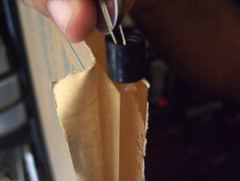
So, a few minutes ago I rigged up and successfully tested a USB connected wall transformer to 1 set of 3 LED's + 1 resistor. Now, it's not fully tested because I need to see if this will be enough to run the entire line but in theory it should be. It is putting out 5V at 1 Amp.
The red wire is connected to pin 1 (+5 live) of the USB and the black wire (0V i.e ground) is connected to pin 4. Pins 2 (Data -5V) and 3 (Data +5V) are for running data - at the moment I'm not concerned with that.
The attached video shows test 1, it's a bit long at 42 seconds so I wouldn't blame you for skipping ahead a few seconds here and there. The point of this test is to show that the wall transformer can pass enough voltage and current through 1 set of the LED's without blowing all the components or generating excess heat. There was no excess heat felt and I think it worked brilliantly for a first test. In the video you see my plugging in the USB end into the transformer connected to the wall and then I pan over to the LED's just before I insert the power connection fully. The light being shown is Infra-red light and not visible to the naked eye. Here it is visible because of the nature of digital cameras and their CCD's sensisitivity to the IR range. With any luck this will be powering the entire display by the end of the week!
Last nights Soldering Party

Last night Juan, Arian and me worked on the frame some. We started by placing the LED's with correct polarity into the baffles. Once we checked they were right we hot glued them in place. After cleaning the leads to the LED's we then prepped them to be soldered. After bending the leads on each of the 66 LED's we ran two wires across the one side of the frame. These will act as a "bus" for electrons to ride into the LED's sets and complete a circuit.
We were able to solder 33 LED's last night and test 1 set of 3 + resistor through the bus line. It worked great. There was only one big problem left to solve - how to we get power from the wall into the bus line?
Tuesday, October 28, 2008
Sunday night LED party!
This is an image of me soldering some electrical components  together. We are soldering 66 LED's though we haven't quite finished yet. We are soldering them in sets of 3's with a resistor attached.
Each set connects all 3 LED's and the resistor in series. Each set of 3 is connected in parallel with every other set of 3. I've provided a really poorly hand drawn diagram of the circuit. It's only part of the circuit, enough to get the gist of what's going on. If you are building your own table and would like an easy way of working the LED circuit then this site is for you: http://led.linear1.org/led.wiz
It gives you an image similar to this (which is the actually circuit I'm using) and looks a lot better. This is what we were aiming to solder but we didn't finish that night and are looking forward to getting some more work done tonight. The most tedious part I would say was to make sure the LED's we were using were not defective or DOA. However, after all that we got to solder and power 1 set of 3 LED's and set them in the housing of the Baffle. I think it looks great!

 together. We are soldering 66 LED's though we haven't quite finished yet. We are soldering them in sets of 3's with a resistor attached.
Each set connects all 3 LED's and the resistor in series. Each set of 3 is connected in parallel with every other set of 3. I've provided a really poorly hand drawn diagram of the circuit. It's only part of the
 circuit, enough to get the gist of what's going on. If you are building your own table and would like an easy way of working the LED circuit then this site is for you: http://led.linear1.org/led.wiz
It gives you an image similar to this (which is the actually circuit I'm using) and looks a lot better. This is what we were aiming to solder but we didn't finish that night and are looking forward to getting some
 more work done tonight. The most tedious part I would say was to make sure the LED's we were using were not defective or DOA. However, after all that we got to solder and power 1 set of 3 LED's and set them in the housing of the Baffle. I think it looks great!
Friday night Frame Party!
What better way to spend a Friday night than with your wife and old friend building and assembling a frame for your crazy project well until the wee hours of the night? I can't think of anything more fun. For those of you who have been following the blog you know that my friend Juan has been helping me a lot along the way with this project since July. Sadly, we are nearing the end of this project.
What follows now are some pictures of Juan and me assembling the frame, priming, and painting it. Enlarging the Slide show and turning the information on ( which means it should read info off - quite confusing but anyway) will show you the comments I have within the slide show.
What follows now are some pictures of Juan and me assembling the frame, priming, and painting it. Enlarging the Slide show and turning the information on ( which means it should read info off - quite confusing but anyway) will show you the comments I have within the slide show.
Tuesday, October 21, 2008
Semi-finished product.
In the image you can see the IR-LED fits snugly and the housing is supporting the LED.
Only thing left to do is clear out small splinters in the holes and paint the baffles. I will paint the side facing the acrylic white and the other sides black. By painting the front white (along with the holes) I will reflect more light into the acrylic. By painting the other sides black the paint will absorb the escaping energy and hopefully reduce any false readings due to light leakage.

Only thing left to do is clear out small splinters in the holes and paint the baffles. I will paint the side facing the acrylic white and the other sides black. By painting the front white (along with the holes) I will reflect more light into the acrylic. By painting the other sides black the paint will absorb the escaping energy and hopefully reduce any false readings due to light leakage.
Sanding some more!
Now I have some good news to share and some bad news. Good news is there are now 2 baffles to line up the LED's 1 inch apart on either side of the acrylic.
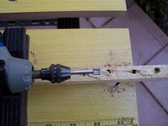
Bad news? Cheap wood means splinters in the LED housings! What to do? Well, this little dremel attachment got rid of a lot of the splinters! However, there are still some smaller bits left over. This will be dealt with in an future post.
Bad news? Cheap wood means splinters in the LED housings! What to do? Well, this little dremel attachment got rid of a lot of the splinters! However, there are still some smaller bits left over. This will be dealt with in an future post.
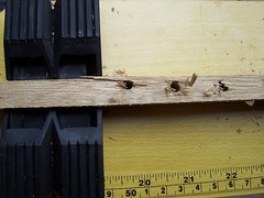
Baffling Templates
So, after I got the first baffle drilled and sanded down enough to sit flat on a level surface I used it as a template. By sitting the first baffle on the second dowel and drilling through the holes and into the dowel I was able to get a second baffle. Although they weren't as perfectly centered as I had hoped it still saved time and kept the alignment of the future LED's.
Dremel to the rescue!
My drill died during the build so I had to look to my dremel for help. This attachment wasn't much but it was better than nothing. Maybe I should have just heated an awl and punched through the wood instead?
Cheap wood
So, the result of using cheap wood was learning a good lesson. Cheap wood splinters easy - that's why it's cheap! Also, I cracked part of my baffle because I forgot that darned center line.
FTIR LED Baffle 2
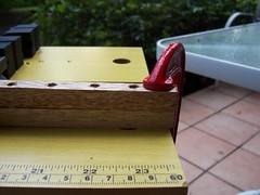
This image is the start of the first baffle. Here I've marked off 1 inch increments with a compass and drilled through them. I forgot to make a center line which made all my holes off centered and haphazard. I've used a 2 or 3" clamp to help me hold the dowel steady while I drill.

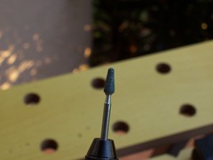
FTIR LED Baffle
I've recently gotten around to making my own baffles to hold the IR-LEDS and to direct the light into the acrylic waveguide. I tried to find a metal U or C channel but I couldn't find the right size anywhere! I decided to use 1/2" dowels from Home Depot - about 50 cents each. I would suggest using better wood or finding a metal channel if you can. The wood splintered and fractured easily, making it a nightmare to work. Here I've shown the led slipping into its new home :).

Friday, October 10, 2008
La Machine's latest and greatest Mechanical Monster!
That's right, you are seeing right, that is a giant 50' Mechanical spider parading itself down the high street in Liverpool, UK. The 50' mechanical beauty strutted its stuff on Sept. 6th and sprayed amazed onlookers with a water cannon in the back of the spider's abdomen! This amazing machine is called La Princess by the engineering group that created her La Machine.
There are more video's like this on youtube and also at www.liverpool-stories.com - Please comment if you have the time.
Sunday, October 5, 2008
FTIR Display Frame pt 3
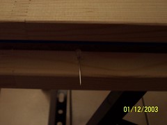
Here I'm checking the clearance of my IR led. The IR LED is Jameco part # 787667. I got 100 for $10! That's without the shipping of course. I was unlucky enough to have them shipped when gas prices were at a record high in July of 08 - $6 for shipping - I was fleeced!
So there is ample room using the canvas stretchers and 3/8" acrylic sheet.
There are notes here so feel free to click on the image and mouse around.
In the future I'd like to get an aluminum C-Channel to fit the led's into and to act as a baffle to focus the light. There is a great instructable I'm following that I will link shortly! Hope this helps anyone out there looking to build a multi touch display! I'll update again when I have more to say!
Measuring the Acrylic pt 2
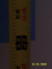
This is a better view of the measurement. Nothing special here - but there are two notes in case you are interested.
Measuring the Acrylic
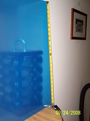
There are notes here as well. To access the notes click on the image and when it loads just mouse around.
Here the measure is 24". This is the way the actual frame will be laid out on the table.
Note the full dimensions are 24" by 32" so as to give a 4:3 ratio.
Here the measure is 24". This is the way the actual frame will be laid out on the table.
Note the full dimensions are 24" by 32" so as to give a 4:3 ratio.
FTIR Display Frame pt 2
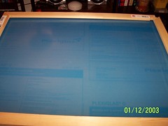
Feel free to click on the image and then mouse around to read my notes.
I've put both acrylic panels together here. They are sandwiched by the wooden canvas stretchers / make shift display frame.
Best part of all - no wood cutting! I will have to drill and thread screws through but that should be a breeze!
I got the canvas stretchers at an art store called Utrecht in Miami. This is near Sunset Place on US 1, about a block away from Pearl. You should be able to get this at any art store or hobby store - search for Canvas stretchers. Also, you can locate an art store near you with these canvas stretchers by visiting www.fredrix.com. But any art store should have them in many different sizes. I found that although my acrylic is 24" by 32" that purchasing 32" by 26" actually fit the screen better.
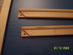
Multi Touch Frame Part 1
Being that have no real word working tools or experience I looked for a way around building my own frame.
Well, I found the perfect solution for me - Canvas stretchers! They come in various sizes and all you have to do is snap them together like wooden Lego's!
Also - the date is wrong. The batteries on my camera died and reset the date to its default setting. The camera is pretty old lol.
The size I'm using here are 24" by 32" for the back and 26" by 32" for the front.
I'm thinking of making the back also 26" by 32" as the arrangement I had in my mind didn't quite work out.
Acrylic Wave Guide and IR light.
Juan was kind enough to take this picture while I made this little make shift baffle. There are notes in the picture so feel free to mouse over.
Sorry for the long over due update!
Sorry for the long over due update!
Subscribe to:
Posts (Atom)